
1. Important
1.1 Safety notes
- Read the instructions before use.
- The product may not be suitable for all people.
1.2 Use
- Use only original parts.
- Do not expose to direct sunlight.
- Keep away from dust, moisture and dirt.
- Do not drop, knock, twist or shake the device.
- PIR II must not be painted over.
- For repairs, contact Telenor e-helse.
1.3 Cleaning
- Clean the device with a soft cloth, moistened with a little mild soapy water.
- Do not clean the device with strong chemicals, solvents or other corrosive substances.
1.4 Recycling
- The device must not be disposed of as general waste. The product must be returned to a recycling facility for correct disposal, or returned to Tellu.
2. Package contents
- PIR II unit
- Mounting bracket
- Door magnet
- AA (LR6) battery x2
3. Areas of use
Motion sensor: The PIR II infrared motion sensor detects movement. A detected movement results in an alarm message being sent to the care provider or the operator at a response centre.
Inactivity alarm: The sensor can also be used to send an inactivity alarm when it has not detected movement within a defined period of time.
Door alarm: PIR II can also be used as a door alarm with detection of passage (Intelligent Door Alarm), with a bypass function.
PIR II is compatible with all NEAT products.
4. Product overview
4.1 Circuit board
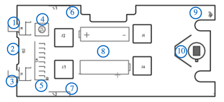
| 1 | ON button (S6) |
| 2 | Operation LED (D2) |
| 3 | OFF button (S5) |
| 4 | Function switch (S1) |
| 5 | DIP switches 1–8 (for configuration) (S4) |
| 6 | REED switch (magnetic switch) (S3) |
| 7 | REED switch (magnetic switch) (S2) |
| 8 | Battery holder (LR06, 1.5 VDC) x 2 |
| 9 | Detection LED (D1) |
| 10 | PIR sensor (D6) |
4.1.1 On and off buttons
The OFF/ON buttons are on the top of the device.
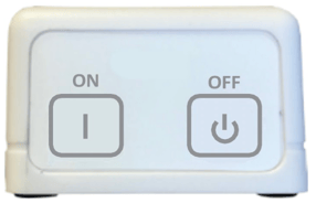
Note! The batteries must be removed to switch the device off completely.
4.1.2 Reed switches
The reed switches (S2 and S3) are magnetic switches that make it possible to use PIR II as a DOOR alarm together with the accompanying door magnet, see "6 IDA (Intelligent door alarm)".
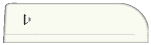
There are two small lines on each side of the PIR II cover to show where the REED switches are placed on the circuit board inside.
4.1.3 Function switch
The function switch (S1) is used for pairing with other radio devices, e.g. a NOVO. See "7 Pairing".
4.1.4 DIP switches
The DIP switches are used for basic device configuration. More advanced configuration is possible with PC software, and this is described further in PIR II Technical Handbook – NE41 19005-02. For an overview of the DIP switch functions, see "13 DIP switch settings".
4.1.5 LED
The operation LED (D2) indicates when alarms are sent, e.g. a user alarm. Technical alarms (e.g. low battery or radio test alarms) are not indicated on the operation LED (D2).
The operation LED also indicates visually when the device starts up and is in walk test mode.
The detection LED (D1) indicates whether the PIR sensor has detected movement.
4.3 IR sensor
4.3.1 Vertical detection area
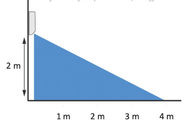
Approximate detection area when mounted on a wall.
It is recommended that PIR II is mounted on a wall, approx. 2 metres above the floor. The detection area then reaches approximately 4 metres into the room from the sensor. The device can also be placed on a horizontal surface, e.g. on the floor, next to or under a bed.
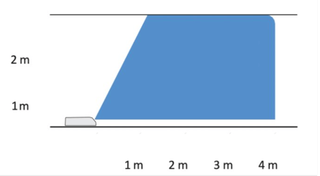
Approximate detection area when placed horizontally.
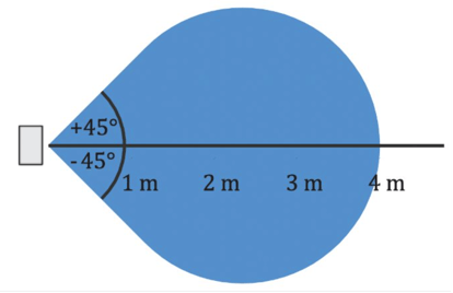
4.3.2 Horizontal detection area
The function switch (S1) is used for pairing with other radio devices, e.g. a NOVO. See "7 Pairing".
4.4 Mounting bracket
The mounting bracket is used to fix the device to a door leaf when PIR II is to be used as a door alarm, see "6 IDA (Intelligent Door Alarm)".
Note! The screws must be 3.5–3.7 mm wide and at least 30 mm long, and the head must not be more than 2 mm high.
5. Using PIR II as a motion detector
The motion detector can also alert when a service user gets out of bed, by placing the sensor under or next to a bed.
5.1 Installation
Place PIR II on the floor next to the bed or on a bedside table. Make sure the device covers the best possible area for the user to trigger a motion alarm. It is recommended to test the placement of the sensor before it is put into live use, and to adjust the placement if needed.
5.2 Configuration
Set the DIP switches according to the table below.
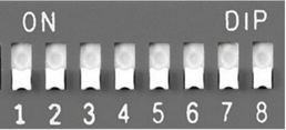
| 1 | OFF (configuration with DIP switches). |
| 2 | ON or OFF, see "13.2 DIP2 – power saving mode". |
| 3 | OFF (PIR II is used as a normal motion detector). |
| 4 | Not in use |
| 5 | ON or OFF, see "13.5 DIP5 – IR detection sensitivity". |
| 6 | ON (alarms are indicated visually). |
| 7 | ON (motion detection is indicated visually). |
| 8 | ON or OFF, see "13.8 DIP8 – Disable OFF button (S5) / Alarm delay". |
6. IDA (intelligent door alarm)
The reed switches and the door magnet make it possible to use PIR II as an intelligent door alarm. The IR sensor, combined with the door magnet, registers that the service user has opened the door. It also registers movement on the inside of the door. If the service user goes out of the door and no movement is detected on the inside of the door after it has closed, the sensor sends an alarm. This reduces the number of false alarms, and avoids alerts when the service user has only opened the door without going out. No alarm is sent when a person comes into the room, because the sensor detects movement on the inside when the door is opened.
The sensor can also be set with a time delay, so that an alarm is only sent if the service user has not come back within the set time. This gives the service user freedom of movement, for example to go to the letterbox or on other short trips.
6.1 Installation
Make sure that the centre of the door magnet is lined up (both horizontally and vertically) with the two vertical lines on the side of the cover, and that the distance between the PIR II cover and the magnet is no more than 5 mm.
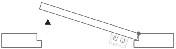
6.1.1 Door that opens outwards
We recommend mounting PIR II on the inside of the outward-opening door leaf (seen from the user's home), and the magnet on the door frame, as shown in the picture below.
6.1.2 Door that opens inwards
When the door leaf (seen from the user's home) opens inwards, PIR II should be mounted on the door frame and the magnet on the door leaf.
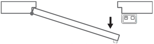
Note! The screws must be 3.5–3.7 mm wide and at least 30 mm long, and the head must not be more than 2 mm high.
6.2 Staff passing
We recommend mounting PIR II on the inside of the outward-opening (seen from the user's home) door leaf and the magnet on the door frame, as shown in picture 9 below.
When care staff or visitors leave the room after a visit, they must press the ON button (S6). The device is then inactive for a period (default 15 seconds), so staff can leave the home without triggering an alarm.
6.3 Configuration
Set the DIP switches according to the table below.
| 1 | OFF (configuration with DIP switches). |
| 2 | No effect |
| 3 | ON (the IDA function is activated). |
| 4 | ON or OFF, see "13.4 DIP4 – IDA, exit alarm delay". |
| 5 | No effect |
| 6 | ON (alarms are indicated visually). |
| 7 | ON (motion detection is indicated visually). |
| 8 | ON or OFF, see "13.8 DIP8 – Disable OFF button (S5) / Alarm delay". |
7. Pairing
To pair a PIR II with a radio device, e.g. a NOVO, start pairing on the NOVO and activate PIR II by pressing the function button S1. Alternatively, add the device manually with the radio ID on the label on the back of the device.
8. Inactivity alarm
The inactivity alarm is turned off by default, and requires configuration from a computer with the PIR program, see PIR II Technical Handbook – NE41 19005-02.
9. Detection test mode
Detection test mode is used to test the coverage area of the IR sensor.
9.1 Activating the walk test function
Activate the detection test function by pressing the ON button for 5 seconds. During the 5 seconds, the operation LED (D2) lights green. After the 5 seconds, it flashes red once every third second, and PIR II is now in detection test mode.
When the sensor is in detection test mode, the detection LED (D1) flashes for 1 second for each detected movement, regardless of the OFF DIP7 setting.
9.2 Deactivating detection test mode
To exit the walk test function, press one of the ON/OFF buttons. If no movement is detected within 60 seconds, PIR II automatically exits detection test mode.
10. Battery check
The sensor checks its battery level at regular intervals. When the battery is below the threshold, a battery alarm is sent.
Battery status is also indicated visually when the ON button is pressed. Normally, the operation LED (D2) turns green for 1 second. At a low battery level, this is followed by 5 quick red flashes.
There is no LED indication when a battery alarm is sent.
11. Radio test alarm
To check the connection with the paired radio device, PIR II regularly sends a radio test alarm.
There is no LED indication when a radio test alarm is sent.
12. Start-up
At start-up, the operation LED (D2) flashes green for 45 seconds, then lights green for 1 second and then turns off.
If the battery is too low, the operation LED (D2) flashes red instead of green during the 45 seconds.
13. DIP switch settings
The settings and functions of the DIP switches are described below.
| 1 | Configuration setting | PC | Local |
| 2 | Power saving function | Power saving | Static |
| 3 | IDA function | Yes | No |
| 4 | IDA, exit alarm delay | Long | Short |
| 5 | IR detection sensitivity | OFF | High |
| 6 | Active LED after alarm | Yes | No |
| 7 | Detection LED after movement | Yes | No |
| 8 | Disable OFF button / Alarm delay | Yes/no delay | No/15 s |
13.1 DIP 1 – Configuration setting
Set to ON for configuration with a computer and NEAT programming software.
- If DIP1 is ON, DIP2 to DIP8 are ignored.
13.2 DIP 2 – Power saving mode
Sending alarms uses battery power. To save battery, PIR II can be set to one of two power states: power saving (DIP2 = ON) or static (DIP2 = OFF).
- DIP2 is ignored if DIP3 is ON.
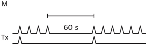
13.2.1 Power saving
In power saving, PIR II sends the first alarm (Tx), and there must then be no motion detection (M) for 60 seconds before PIR II sends a new detection alarm (Tx).
Any motion detection (M) within the 60-second time frame is ignored, and the timer is reset to 60 seconds.
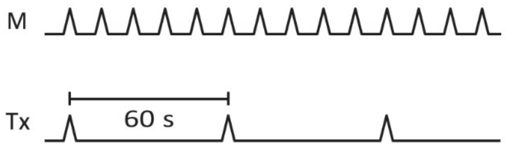
13.2.2 Static
In static, PIR II sends an alarm (Tx) after the first motion detection (M) and ignores new motion detections (M) for 60 seconds before a new alarm (Tx) is sent.
13.3 DIP 3 – IDA function
Set to ON to activate IDA (Intelligent door alarm).
- If DIP3 is set to ON, DIP2 and DIP5 are ignored.
- If DIP3 is set to OFF, DIP4 is ignored.
- DIP3 decides the function of DIP8.
13.4 DIP 4 – IDA, exit alarm delay
In IDA, this setting decides the delay for an exit alarm. When set to ON (Long), the exit alarm is delayed for 180 seconds after a motion detection, while OFF (Short) delays the exit alarm by 5 seconds.
- DIP4 is ignored if DIP3 is set to OFF.
13.5 DIP 5 – IR detection sensitivity
Set to ON for low sensitivity and OFF for high sensitivity.
- DIP5 is ignored if DIP3 is set to ON, and the sensitivity is then automatically set to high.
13.6 DIP 6 – Operation LED after alarm
Set to ON to make PIR II indicate with the operation LED (D2) when an alarm is sent.
The operation LED always indicates start-up, regardless of this DIP setting.
13.7 DIP 7 – Operation LED after movement
Set to ON so that PIR II indicates with the detection LED (D1) when a movement is detected.
13.8 DIP 8 – Disable OFF button (S5)/Alarm delay
This function depends on whether DIP3 is set to ON or OFF.
13.8.1 If DIP 3 is set to ON (IDA is activated)
Set DIP8 to ON:
- The OFF button (S5) can be configured, and alarm delays depend on DIP4.
- The OFF button (S5) has no effect, i.e. it has no function, and the device cannot be switched off with the OFF button (S5). This can be useful to stop users from switching off the device by accident.
Set DIP8 to OFF:
- The device can be switched off with the OFF button (S5).
13.8.2 If DIP 3 is set to OFF (IDA is not activated)
The OFF button (S5) can be configured, and alarm delays can be set.
Set DIP8 to ON:
- The OFF button (S5) has no effect, i.e. it has no function, and the device cannot be switched off with the OFF button (S5). This can be useful to stop users from switching off the device by accident.
- There is no alarm delay.
Set DIP8 to OFF:
- The device can be switched off with the OFF button (S5). This is useful for care staff and visitors who come into the room in the morning: by pressing the OFF button (S5) they stop an alarm from being sent, and the alarm can be switched off during the day.
When the ON button (S6) is pressed while the device is switched off, motion alarms are not registered until 15 seconds have passed. This is useful when the device is used as a bed alarm.
- The alarm delay is set to 15 seconds.
14. Technical data
| Dimensions (W x H x D) | 57 x 128 x 35 mm |
| Weight (without batteries) | 82 g |
| Power supply | 3 VDC |
| Battery type | (AA) LR06, 1.5 V |
| Transmit frequency – EU | 869.2 MHz (Social alarms) |
| Max transmit power | 869.2 MHz 10 mW (EIRP) |
| Bandwidth | 25 kHz |
| Temperature range | +5 to +55 °C |
| IP class | 20 |